Cloning a Vox practice amp - the AC4
AX84 - an inspiration
A couple of years ago I stumbled over a very interesting
site on the internet which was all about building your own valve
amp. That site was Cooperative
Tube Guitar Amp Project - AX84.
They had a project, ideal for beginners like myself, called the P1
which many first time builders had already successfully completed.
I started studying the schematics and Dave Sorlien's excellent
theory document, putting my electronics degree to good use for the
first time in many years. Not that they taught us anything about
valves at university. In the
late 80's it was all VLSI and programmable gate arrays.
Ever since I decided to take up the guitar at the age of 30 I'd
fantasised over owning a Vox AC30, at the same time realising that
my guitar playing ability and the fact that I'm only likely to
be playing in my own basement didn't warrant such an expensive and
powerful amp. That was no reason not to apply what I'd learned
about the AX84 P1 to another single-ended EL84 design, Dick Denny's
Vox AC4 practice amp.
AC4 - round one
I'm not going to say much about my first attempt at building this
amp. It kind of worked. The trannies and valves turned out to be
too big to hang upside down in my Fender Frontman 15R cabinet, so
that was the end of that idea. The oscillator circuit seemed
to behave oddly. The chassis was very cramped and the
wiring, being a mixture of true point-to-point and terminal strips,
was a mess. I put it away, slightly disheartened, then moved house
and forgot about it for a while, playing through the Laney LC15R
instead.
Harald arrives on the scene
Harald being my son, born in October 2001. At the age on one he
wasn't particularly fond of being woken by a cranked Laney after about
eight o'clock in the evening. Come to that, my wife Kristin isn't
too impressed when I drown the telly out either. In September 2002
I was off work on paternity leave and decided it would be
a great idea to rebuild the AC4 - properly this time. So as Harald
napped in the middle of the day I'd be down in the workroom cutting
and drilling aluminium, or soldering, or checking the internet for
parts. And when he woke, I'd drag him off to the hardware store or
electronics suppliers for aluminium sheet, or pine boards or
hookup wire. He didn't seem to mind.
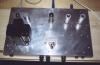
The chassis

The local hardware store had 2mm aluminium sheet cut to 400x250mm.
That seemed like a decent starting point and would give me plenty
of space to mount all the parts. I could probably have gotten away
with using half the sheet, and I can't help thinking that the
finished amp is a teensy, weensy bit overdimensioned in relation
to its output power. However, I felt vindicated recently when looking
at the pictures of Chris Hurley's P1 Rev.11 on the AX84 site. His
chassis is at least as big as mine if not bigger!
The sides of the chassis were made from profiled aluminium, mitred
in the corners and riveted to the aluminium sheet once all the holes
were drilled and/or filed for pots, connectors and fuses.
Transformers
When I started looking for parts, the only supplier I knew of in
Norway was Arnold Goksøyr at
Demostenes. He mostly caters to the hi-fi market and stocks
transformers from the Italian manufacturer Novarria. He had a
250-0-250@100mA power transformer with 6.3V@3A and 5V@2A heater
windings. He also advertised a Hammond output transformer matching
the description of a 125C. Unfortunately there had been a mix up
at his supplier's, and he had recieved the wrong stock. By the
time he realised this, he'd already sent me a Hammond 125H. The 125H is
an 8W/60mA universal output transformer with a 10KOhm centre-tapped
primary, into a 4 or 8 Ohm load. Cue som head scratching,
as I wanted a single ended 5K primary. I mailed Arnold and
we agreed that it should be possible to use one half of the
primary, from the centre tap to one of the ends, for a 5K load.
Not an ideal solution, but the result was surprisingly good.
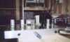
The 125H is at an inherent disadvantage compared to a dedicated
single ended output transformer as it lacks an air gap. This makes
it susceptible to magnetic saturation caused by the single ended DC
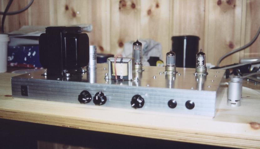
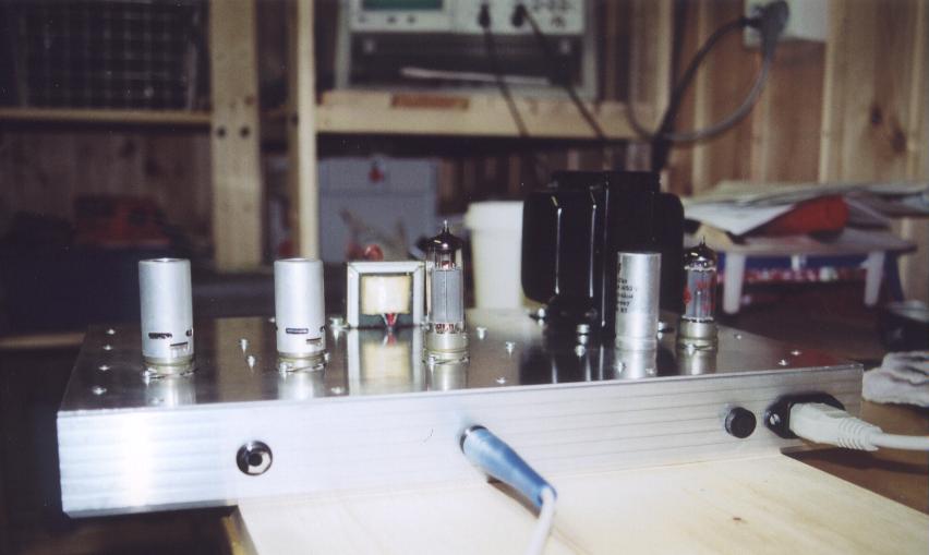
current. As the pictures show the 125H is tiny - it is dwarfed by the
power transformer. The lack of physical size results in relatively
poor low frequency performace. Not entirely satisifed with this
solution, I got in touch with Sixten Forsén at
Edgar Audio in Sweden who
stocks the full Hammond range of audio transformers and chassis.
I placed an order for a Hammond 125C-SE, one of a fairly new range
of output transformers specifically designed for single ended use.
Sixten was extremely helpful and friendly and I can thoroughly
recommend him to anyone looking for valve amplifier parts in the
Nordic countries.
Update 21.08.2003
The 125C-SE has been in place for quite a while now and I'm extremely
happy with the improvement in sound quality. That 125H is going to
go into a little push-pull project at some point in the future.
The valves
So far I haven't played too much with different valve types. The EL84
I'm using is a Brimar which I believe to be NOS. It was given to me
by a colleague who once upon a time worked as a ship's radio operator.
He gave me a bunch of other valves too and some of these will be
turning up in later amp projects.
The EF86 in the input stage is NOS Mullard, bought from
Demostenes. I have a new Svetlana
and a used Siemens that I intend to try, but for now I'm very
happy with the Mullard ;-) The ECC83 position in the tremelo circuit is
filled by a JAN Philips 12AX7WA.
When these picures were taken I was using a National branded EZ80
recitifier. I found the B+ to be a little on the low side and playing
with Duncan's PSU Designer
I reckoned that an EZ81 should give me about 15V more and bring me
closer into line with the original Vox values. Cue a Haltron branded
NOS EZ81, once more from
Demostenes. The software was absolutely spot on and I'm very happy
with the voltage levels now.
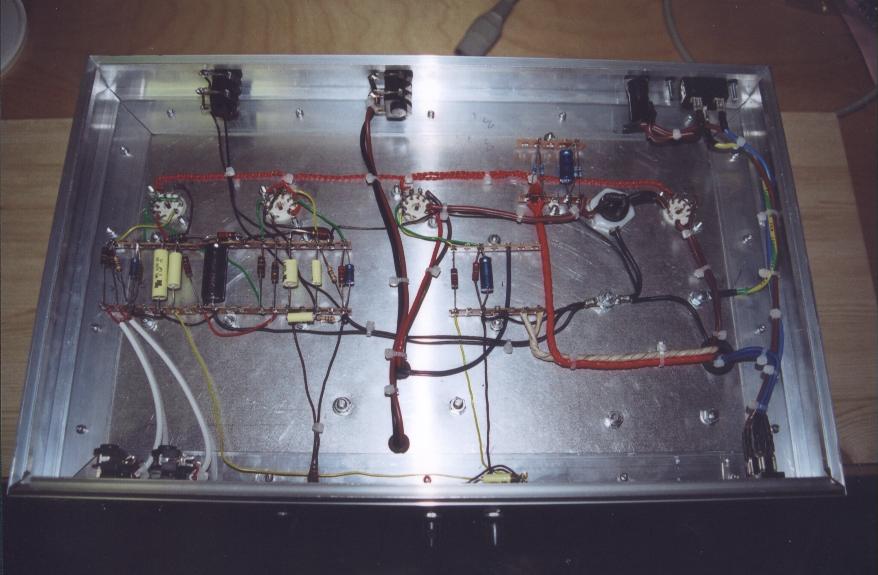
The layout

Based on what I'd read on the AX84 site, the preferred building method
seemed to be a turret board. The electronics supplier I was using,
Elfa, had neither turrets nor unclad
circuit boards, so I fell back on the good old terminal strips. Not to
be outdone, I decided to do a layout based on parallel rows of terminals,
approximating a turret board style design.
I drew up the chassis in full scale on graph paper and started placing
the major components. I'd picked a chassis mounted 33+33μF filter
capacitor which I placed next to the rectifier socket behind the power
transformer.
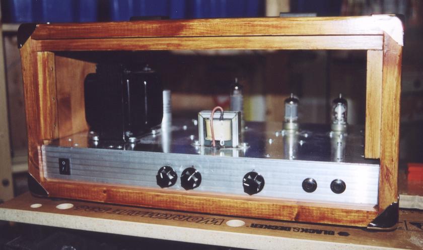
A head cabinet